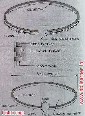
There are two types of piston rings:
1. Compression rings. 2. Oil control rings.
 |
|
8.camshaft:-A cam shaft is simply a shaft on which cams are mounted. The cam shaft is mounted in bearings in the lower part of the cylinder block in most in-line engines. In a few engines it is located on the cylinder head. In V-8 engines it is located between the two banks of cylinders.A cam is a device that changes rotary motion of the cam shaft into linear motion of the follower or lifter. The cam has high spot or lobe. The follower riding on the cams will move away from or toward the cam shaft as the cam rotates.The cam shaft is driven by the crankshaft either by a pair of meshing gears (timing gears) or by means of a pair of timing sprockets connected by a chain. The cam shaft gear or sprocket has twice as many teeth as the gear or sprocket on the crank shaft. This gives 1 : 2 gear ratio, the cam shaft turns at half the speed of the crank shaft. Thus, every two revolutions of the crank shaft produce one revolution of the cam shaft; and one opening and closing of each valve, in the four-cylinder engine. The gear and sprocket maintain a definite time relationshipbetween the cam shaft and crank shaft to insure opening the valves exactly at the correct time in relation to piston position. Timing marks on the gears and sprockets are used to set the shaft in correct time with each other when the units are assembled. In the small circles on the crank shaft timing gear must fall between the two small circles on the crank shaft timing gear to insure correct valve timing. The marks of the sprockets are in a straight line with the centres of both shafts to insure correct valve timing.

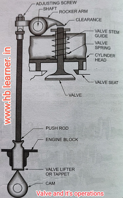
9,10> valve and it's operation:- Valve is a device to close and open a passage. In motor vehicle engines, two valves are used for each cylinder - an inlet or intake valve and an outlet or exhaust valve. Fuel is admitted to the cylinder by the inlet valve, and the burned gases escape by the exhaust valve. When closed, the valve must seal the combustion space tightly. The valves are usually made of austenitic stainless steel which is a corrosion and heat resisting material. Exhaust valve is usually made of silchrome steel which is an alloy of silicon and chromium with unusual resistance to heat. Inlet valve being subjected to less heat is usually made of nickel chromium alloy steel.
Overhead Poppet Valve Mechanism. the valve mechanism to operate the valve when it is in the cylinder head (in /-and F-head design). This type of mechanism requires two additional moving parts-the push rod and the rocker arm. As the cam rotates, it lifts the valve-tappet or the lifter which actuates the push rod. The push rod rotates the rocker arm about a shaft- the rocker-arm shaft, or a ball joint in some designs to cause one end to push down on the valve stem to open the ck valve, thus connecting the valve port with the combustion chamber.
11,12> Intake, Exhaust Manifold:- The exhaust manifold is a tube for carrying the exhaust gases away from the engine cylinders. It collects exhaust gases from the exhaust ports of the various cylinders and conducts them to a central exhaust passage.The exhaust manifold is usually made of cast iron. It is bolted to the side of the cylinder block on L-head engines and to the side of the cylinder head on I-head engines. On V-8 engines, there are two exhaust manifolds, one for each bank of cylinders. On some V-8 engines, each manifold is connected to a separate exhaust pipe, muffler and tail pipe. On others, they are connected by a crossover pipe and exhaust through a common muffler and tail pipe.
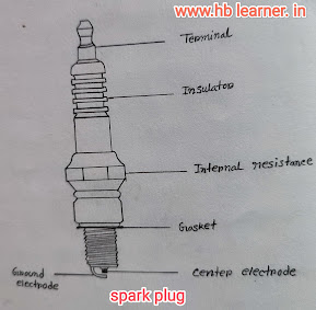
13.spark plug:-Spark plug is a device to produce electric spark to ignite the compressed air-fuel mixture inside the cylinder. The spark plug is screwed in the top of the cylinder so that its electrode projects in the combustion chamber.Construction. A spark plug consists of mainly three parts:
1. Centre electrode or insulated electrode.
2. Ground electrode or outer electrode.
3. Insulation separating the two electrodes.
The upper end of the centre electrode is connected to the spark plug terminal, where H.T. cable from the ignition coil is connected. It is surrounded by porcelain insulator. The lower inalf portion of the insulator is fastened with a metal shell. The lower portion of the shell has a short electrode attached to one side and bent in towards the centre electrode, so that there is a gap between the two electrodes. The two electrodes are thus separated by the insulator. The sealing gaskets are provided between the insulator and the shell to prevent the escape of gases under various temperature and pressure conditions. The lower part of the shell has screw threads and the upper part is made in hexagonal shape like a unt, so that the spark plug may be screwed in or unscrewed from the cylinder head.
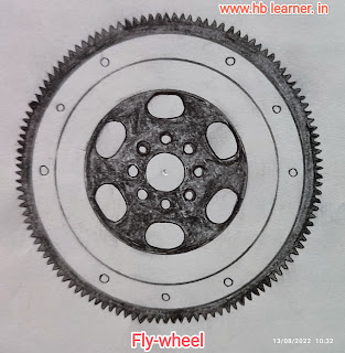
14.Fly-wheel:- A flywheel is a fairly heavy steel wheel attached to the rear end of the crankshaft. The size of the flywheel depends upon the number of cylinders and the general construction of the engine.
The flow of power from the engine cylinders is not smooth. Although the power impulses in a multi-cylinder engine overlap or follow each other to provide a fairly even flow of power, however, additional levelling of power impulses is required. This is done by a flywheel.
To understand the function of a flywheel in a better way, take the example of a four-stroke, single-cylinder engine. There are times when more power is being delivered than at other times. This tends to make the crankshaft speed up and then slow down.The engine delivers power during one stroke only the power stroke; and it absorbs power during the other three strokes-to push out the exhaust gases, to intake fresh charge in the cylinder and to compress this charge. Thus, during power stroke the engine tends to speed up and during the other three strokes it tends to slow down. The inertia of the flywheel tends to keep it running at constant speed. When the engine tends to speed up the flywheel resists it. When the engine tends to slow down, the flywheel resists it. Thus, the flywheel absorbs energy as the engine tries to speed up and gives back energy as the engine tries to slow down, keeping the engine speed almost constant. In multi-cylinder engine, the flywheel acts in the same way to smooth out still more the peaks and valleys of power flow from the engine.
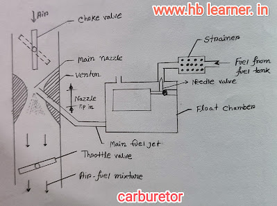
15.Carburetor:- The carburetor is a device for atomizing and vaporizing the fuel and mixing it with the air in varying proportions to suit the changing conditions of spark ignition engines. The air-fuel mixture so obtained from the carburetor is called the combustible mixture. The process of mixing the gasoline fuel with air to obtain the combustible mixture is called carburetion.
Hence, the terms vaporization and atomization should be understood clearly. Vaporization is the change of state of the fuel from liquid to vapor. Atomization is the mechanical breaking-up of the liquid fuel into small particles (but not actually breaking-up into atoms, as the name implies) so that every particle of the fuel is surrounded by air. In order to produce very quick vaporization of the liquid fuel, it is sprayed into the air passing through the carburetor. Spraying of the liquid turns it into many fine particles, so that the vaporization occurs almost instantly.
The carburetor supplies the air-fuel mixture of varying proportions to suit the changing conditions of the engine. The mixture must be rich (have a higher percentage of fuel) for starting, acceleration and high speed operation. The mixtures should be lean (have a lower percentage of fuel) for operation at intermediate speed with a warm engine. The theoretically perfect mixture of air and gasoline contains 15 parts of air and part of gasoline by weight. An ideal carburetor would pass the mixture of completely vaporized fuel and air in the proper proportion to the intake manifold and cylinder. But in the present-day carburetors, the complete vaporization of fuel is not achieved, due to the heavy nature of fuel and other limitations. The heated intake manifold and hot spots in the manifold vaporize part of atomized fuel. Even until the end of the compression stroke in the cylinder, the gasoline does not vaporize completely, although the heat and pressure during the.
16.Radiator:- Radiator is a device for having a large amount of cooling surface to the large amount of air so that the water circulating through it is cooled efficiently. It consists of an upper tank and a lower tank and between them a core. The upper tank is connected to the water outlet or outlets from the engine jacket by a hose pipe; and the lower tank is connected to the jacket inlet through the water pump. The core is a radiating element, which cools the water.There are two basic types of radiator cores-tubular type and cellular type. In tubular type core the upper and lower tanks are connected by a series of tubes through which water passes. Fins are placed around the tubes to improve heat transfer. Air passes around the outside of the tubes, between the fins, absorbing heat from the water in passing. In cellular type core, air passes through the tubes and the water flows in the spaces between them. The core is composed of a large number of individual air cells which are surrounded by water. Because of its appearance, the cellular type is usually known as a honeycomb radiator, especially when the cells are hexagonal in form.In a tubular radiator, because the water passes through all the tubes, if one tube becomes clogged, the cooling effect of the entire tube is lost. In a cellular radiator, the clogging of any passage results in a loss but of a small part of the total cooling surface.
Radiators are also classified according to the direction of the water flow through them. In some, the water flows from top to bottom-down flow type radiators. In other, the water flows horizontally from an input tank on one side to another tank on the other side-cross flow type radiator.
Radiators are usually made of copper and brass because of their high heat conductivity. The various sections of the radiator are almost completely joined together by soldering.
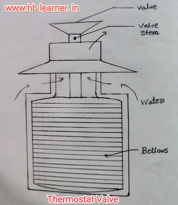
17.Thermostat Valve:-A thermostat valve is used in the water cooling
system to regulate the circulation of water in system to maintain the normal working temperature of the engine parts during the different operating conditions. The thermostat valve automatically works in the cooling system. When the engine is started from cold, the thermostat valve prevents the flow of water from engine to radiator so that the engine readily reaches to its normal working temperature, after which it automatically comes into action. Generally, the thermostat valve does not permit the water below 70°C. the water cooling system using the thermostat valve.
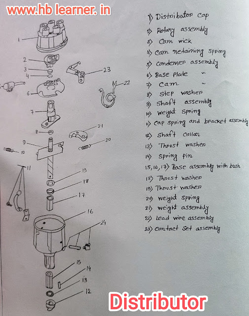
18.Distributor:-The distributor consists of a housing, driving shaft with breaker cam, breaker plate with contact points, governor, condenser, rotor, advance mechanism and cap. The shaft is driven by the engine cam shaft directly or indirectly through the oil pump drive shaft. The drive shaft is rotated at half the engine speed in four-stroke engines. When the shaft moves, it opens and closes the breaker points. The breaker cam contains the same number of lobes as the number of cylinders in the engine. Arotor is mounted on the breaker cam which is carried by the drive shaft. The rotor connects the centre terminal of the cap with each outside terminal in turn, so that high voltage surges from the coil are directed first to one spark plug and them to another, according to the firing order.
19.ac mechanical pump:-This is a Diaphagm type pomp. The Diaphy is made of a great cotton imprega impregnated with synthtic high great robber having two value (NAV) ane made of bakelite which is So light to Keeps the enertia stresses minimum the drive of the pump is taken from camshaft by means of an Eccentric com the eccentric operate rocker arm while in Conjuction with Dinghy nowon spring pushes the diaphangen op op and down during Diaphagm which causes movement the inlet side to goes though the strainer to casues vacum in the chamber open and the fuel than the chamber. The next upward movement of the Diaphagm causes the inlet valve to close while the outlet valve open and feel goes to the Carburetor float.20.Lubricating system:- wet sump lubricating System (ii) Dry Sump lubricating system. Buttom of the Crankcase Contains and oil Pan or Sump
from which the lubricating oil is Pumped to verious Compained of the engine inside and outside both by the Lubricating pomp and after Lubricating the parts of the engine lubricating oil flows back to the pump by gravity. There are 3 vanities types of wet Sump
Lubricating System @ stlash Lubricating
System stlash and pressure system
Stlash lebnicating system
This type of Lebricating system used in light duty engine. The lubricating cond a oil Change into the buttom of the crankcase maintained at pre-determined leal the oil is drawn Pump delivered to a distributing pipe into and slash through in stlasher on dipped is provided under the each conecting rod cap.stlash and pressione system
under pressureto main
The Lubricating oil is bearing, big end bearing and Encamshaft bearing the oil also Sopplied onder pressure bearing also do all pipe and Crank Pin Lubricated by the stash. Pressure feed system
main tamed engine oil Pressite of both Low idle and high Idle of the hole is driving from the center of each crank pin. to the center of in adjusting of main Journal through which oil Chaakpass to main bearing to crank pin
(2) Day Sump Lubricating Budem
an In this system oil is cooked in external tank and oil Pump Grows oil from the supply tank circulate is under Pressure to the various bearing of the engine dripping oil the ginder bening into the Semp is removed by and Scave ging pomp which in trom the all is first to filter cand fed back to supply tanko the exparity of sewering pump this always batter than Lubricating oil pump a separate Oil Cooler provided to ree lubricating oil.
1 Gravity
2) The flash point
3) viscosity
4 Cloud Point
5 Pour point
6) Carbon residue test
7 Ash test
8) Precitition Number
All details about engine components in automobile.


.png)


No comments:
Post a Comment