Alternator(A.C Generator) Principle
ALTERNATOR (A.C. GENERATOR) PRINCIPLE:-
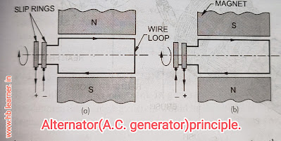
In D.C. generator, the conductors are rotated in a stationary magnetic field and current flows in the same direction. But in A.C. generator, the magnetic field is rotated and the conductors remain stationary. The current flows first on one direction and then in other alternately.
As shown in a rotating bar magnet furnishes the moving field which cut the U-shaped conductor. As at (a), when the north pole passes the upper leg of the conductor, the current flows in one direction. As at (b), when the south pole passes the upper leg of the conductor, the direction of the magnetic lines of force is reversed and the current flows in reverse direction in the conductor. Thus, the magnet is revolving continuously, the direction of lines of force is also changing continuously, the current alternate in direction-alternating current flows. The strength of current depends upon the following factors:
1. Strength of the magnetic field.2
. Speed of the magnetic field with which it revolves. 3. Number of conductors.
Instead of a simple bar magnet, two or more pole pieces, having field winding, are assembled on a shaft. When the current flows in the winding, a strong magnetic field is created and the pointed ends of the pole pieces become alternately north and south poles. The two ends of the conductors are connected to the two slip rings fixed on the shaft. The brushes make continuous sliding contact with the slip rings, through which the current is taken out to an external circuit for transmission and distribution.
The alternator type generator differs from the commutator type generator in the method of voltage and current control and also in design. It uses silicon diodes to change the alternating current to direct current for the vehicle's electrical system. Also, it does not require any cutout to prevent the battery from discharging through it, because the diode rectifiers allow the current to flow in one direction only.
Construction of Alternator:-
Shows rotor of an A.C. generator. The rotor consists of a circular field coil encased by two end pole pieces, each having six protruding fingers spaced 60 degrees apart. These fingers are alternately spread to provide twelve poles. The end of the field coils are connected to the slip rings.
The carbon brushes make sliding contact with the slip rings, through which the current is taken out to an external circuit. The rotor is mounted on a shaft supported in the front by ball bearings and in the rear by needle bearings. A pulley is keyed at the front end of the shaft to turn by means of an engine driven belt.
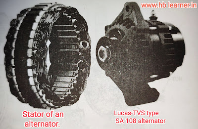
 The stator of A.C. generator consists of an internally slotted, laminated iron core around which three sets of windings are made. One of each winding is connected to a common Y-junction. The other end is connected to one positive diode rectifier and one negative rectifier.
shows the charging circuit of A.C. generator. When the ignition switch is turned on, the rotor receives current from the battery through the voltage regulator. This current produces the magnetic field of the rotor. As the rotor is turned by the pulley, current is induced in the stator winding. This alternating current is changed into direct current by rectifiers. The voltage depends upon the rotor speed. A voltage regulator is used to limit the generator voltage to a correct value.
RECTIFIERS:-
The A.C. generator of the alternator produces alternating current. It is to be converted or rectified to direct current because the battery ignition system and other electrical components of the automobile are all D.C. units. To change the alternating current to direct current, six silicon diode rectifiers are used. The diode is an electric device that permits current to flow through it in one direction only. The three positive rectifiers are pressed into a heat sink (an insulated die cast aluminum holder) which is electrically insulated from the generator frame. It is large enough to dissipate the heat generated by the rectifiers. The positive rectifiers are connected to the battery terminal of the generator and the negative rectifiers are grounded by being pressed into the rear aluminum frame.
By turning on the ignition switch, the rotor receives current from the battery through the voltage regulator. This current energizes the rotor field magnets, which induce a current in the stator windings as the rotor is turned by the pulley. The induced alternating current is changed to direct current by the rectifiers.
GENERATOR CONTROL:-
If the full charging current is generated at low engine revolutions, the charging current would be excessive at higher engine revolutions and may damage the battery and the general electrical system. The generator output must automatically adjust itself to the electrical needs of the vehicle. The charging rate of the generator must be adjusted to the condition of the battery, a high rate for a low battery and a low or no rate for a fully charged battery. Also, the battery must be disconnected from the generator when it is not being turned; and reconnected when it is able to furnish electrical energy. Therefore, it is necessary to introduce some means of controlling the voltage or the current. By generator control (or regulation) we mean preventing the generator from producing excessive voltage and current without any control, a generator would continue to increase its output as speed goes up until it would be producing so much current that it would overheat and burn up.
REGULATORS FOR A.C. GENERATORS
Various types of regulators for A.C. generator are developed in recent years. Some operate and are adjusted like those for D.C. generators. Others have no moving parts at all. A popular type has been described here.
shows the wiring circuit of a voltage regulator for A.C. generator. In this system, only the voltage is to be regulated. When the voltage reaches to a predetermined value, the regulator contact points open to insert resistance into the generator field circuit and thus prevent excessive voltage. The contact points of the regulator vibrate to maintain a steady voltage. There are two sets of contact point in this regulator-a lower set and an upper set. At intermediate speeds, the lower contact points vibrate to open and close; and control the generator voltage. This action inserts and removes the resistance in the generator field circuit. At higher speeds, the higher voltage generator causes the upper contact points to vibrate. When the upper contact points are closed, the generator field winding is shorted, that is, both the ends are connected to ground, so that further voltage regulation is obtained. Thus, the voltage is properly regulated throughout the full range of generator speed with the help of two sets of contact points.
The system does not require current regulator and cutout relay.The current flows only in one direction to charge the battery. The diodes prevent the current to flow in reverse direction. When the generator slows or stops, the battery cannot discharge back through the generator, even though the two still remain connected to each other. When the ignition switch is turned off, the field is disconnected from the battery to prevent any drain on the battery, when the engine is not running.
CUTOUT RELAY:-
The cutout relay (or circuit breaker) closes the circuit betweenthe generator and the battery when the generator is producing current. Also, it opens the circuit so that the battery cannot discharge back through the generator when the generator stops or slows down. The D.C. generator is connected to the battery through a cutout relay and an ammeter.
The cutout relay is simply a magnetic switch. It consists of two windings shunt winding and series winding, assembled around a core and a flat steel armature mounted on a hinge above the core. The series winding consists of a few turns of heavy wire and the shunt winding consists of a few turns of fine wire. The armature is connected to the battery through an ammeter by contact points.
When the generator is not operating, a spring on the armature holds the contact points apart, this keeps the circuit between the generator and the battery open. When the generator is operating, the core winding creates magnetic field which attract the armature, contact points are closed and generator is connected to the battery. Current flows from the generator to the battery and passes through the series winding. But when the generator stops, the current begins to flow from battery to generator. This reverse direction of current flow in the series winding causes the magnetic field to reverse. Thus, the magnetic fields of the winding no longer aid and is so weakened that it cannot hold the armature down. The spring tension pulls the armature up, separating the contact point. This opens the circuit between the generator and the battery.
AMMETER:-
Ammeter is connected in the charging circuit between the battery and generator to show how much current is flowing to the battery during the charging; and how much current is flowing from the battery during the discharging. Ammeter is fitted on the instrument panel infront of the driver. It is used in most of the vehicles, however, an indicator lamp is also used in some vehicles to indicate whether or not the generator is charging the battery.shows the simplified diagram of a car ammeter. It consists of a pivoted vane to which a needle is attached, a permanent magnet and a heavy conductor. The needle moves on a graduated scale, one side of which indicates charging current and the other side discharging current. At the centre, zero is marked. When the needle points zero, no current flows to or from the battery, the pivoted vane is held between the two poles of the permanent magnet. When the current flows to the battery, needle swings to "charge" side. When the current flows from the battery, the needle swings to "discharge" side. When the current flows in any side, it passes through the conductor. The magnetic field forces the vane to move. The stronger the current, the farther the van moves. Therefore, the needle swings on the scale point in the amount of current flowing through.
Details about :- 🖍🖍🖍🖍🖍🖍🖍🖍🖍🖍🖍🖍
Alternator(A.C Generator) Principle


No comments:
Post a Comment